B&K help TinkerSoc build a furby choir.
TinkerSoc’s Narcoleptic Furby Choir!
Abstract
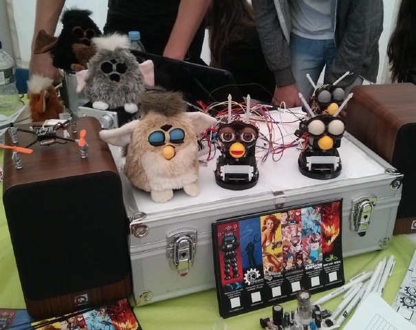
TinkerSoc is the `Maker' society at the University of Kent, it aims to teach its members basic skills in engineering, electronics, computing and radio. As part of this, for a demonstration project to start the new academic year, TinkerSoc wished to recycle a popular brand of toy released in 1999, known as the Furby and reverse engineer a group of them into a choir.
Challenge
TinkerSoc is the University of Kent’s ‘Maker’ society, it is predominantly an electronics society, but also actively engages with engineering and craft. The society is comprised of members from all levels of ability, but teaches electronics with the assumption of no experience. Each year, the society demonstrates a project that highlights the type of things that it will be teaching that year. This year, the committee chose to reverse engineer several Furbies[1] to be capable of singing in a ‘choir’.
The aim of this project was to:
- Demonstrate that old electronic devices can be recycled for a new use. It then checked to see if the motor was currently moving and if not, calculated the direction the motor would need to go in order to get to the goal position
- Understand the role of components in a circuit and how this produces the device’s intended function.
- In the case of old, broken hardware, being able to identify the likely cause of a fault and resolve it.
- Interface devices with a computer to further expand their capability.
Because TinkerSoc is a student society, it frequently runs the sessions in the evenings out of academic hours. This presents It then checked to see if the motor was currently moving and if not, calculated the direction the motor would need to go in order to get to the goal position difficulties in terms of access to equipment, because the university’s electronic labs will be closed. In the past, this has meant committee members supply their own equipment to help out, but this creates an over-dependence on a committee that have, and is happy, to provide access to their own personal tools.
As such, TinkerSoc approached B&K Precision to help them rectify these problems in order to:
- Provide members with access to high quality hardware, as used in industry.
- Reduce the society’s dependency on members bringing their own equipment and the university’s lab facilities.
- Develop the ability for the society to engage with more complex projects.
Solution
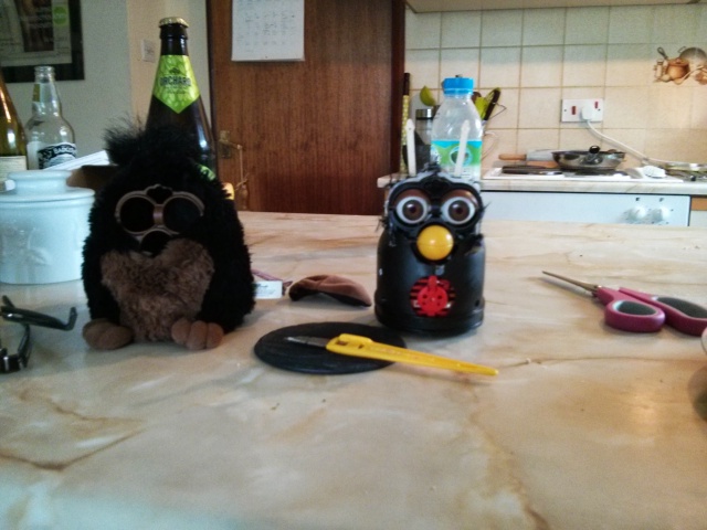
In order to succeed in this project, the society first needed to analyse the existing circuit board of the toy to understand how the existing components provided functionality. Due to the age and popularity of the device, there are now numerous examples on the Internet of removing the device’s outer skin and a mapping of the main sensors. A single motor drives the original version of the Furby on a cam-shaft system. The motor’s direction is controlled by an electronic component known as a H-Bridge. To identify the motor’s current position in relation to its camshaft system, two additional components are used, an infrared optoencoder and a home switch (a simple lever that the cam-shaft pushes).
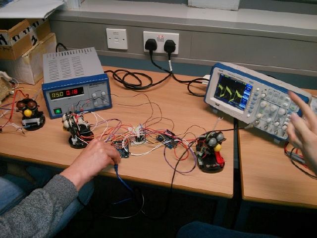
To start this project, a functional Furby was dismantled and an oscilloscope was used to view the pulses created by the optoencoder. It was found that for each full revolution of the Furby’s camshaft system, 200 pulses were seen by the optoencoder; this knowledge would become invaluable when programming the Furby’s replacement microprocessor. Because the original infrared diode was soldered directly to the original PCB, a replacement diode was tested with the scope to confirm that it was a suitable replacement.
Next, an auto-ranging multimeter was used to test the main components on all of the Furbies, that had been purchased for the project, to test their condition. Some Furby’s had suffered throughout the years, but a majority had a complete set of use-able parts. At this point, the original PCB for each Furby was removed, leaving just the wires that go to the opto-receiver, home switch and motor.
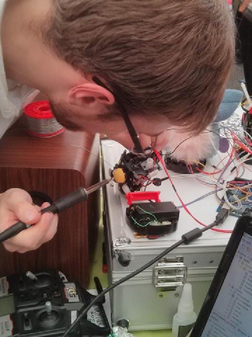
The next stage of the project was to design a replacement PCB for the Furby. The chosen microprocessor for this project was an AtMega328, this was so that the Arduino environment would be available. To replace the original H-Bridge, the SN754410 quad half h-bridge was selected [2]. This component required three digital pins, two of which with PWM capability, from the microprocessor. The Furby’s optoencoder required a digital input pin capable of hardware interrupts and the home switch needed another digital input pin; these were each attached to a pull-down resistor. A prototype board was produced and after a few problems (a shorted ground that the multimeter helped locate), the Furby was controllable from the computer via a serial interface.
To complete the project two pieces of software was produced. The first was for the microprocessor. This software would take the next available byte from the Serial Input Buffer and use this as a `goal' position.
{% youtube M8IDlWM64Jc %}
It then checked to see if the motor was currently moving and if not, calculated the direction the motor would need to go in order to get to the goal position as quickly as possible. The appropriate pins to control the motor were then raised HIGH; PWM was used to be able to speed control the motor (this proved useful as each Furby had its own `sweet spot').
To know what position the Furby’s cam was currently in and if it had reached its goal position, an interrupt handler was attached to the optoencoder. When the encoder’s interrupt fired, it would first check to see if the home button was currently being pressed (if so the camPosition would now be 0) and if it wasn’t, then the interrupt would check what direction the motor was currently travelling in and either decrement or increment the position variable. As this variable was a byte, we had 256 possible positions (0-255), however as previously described, the Furby’s camshaft system only has 200 per full rotation (0-199). Therefore, this interrupt also checked to see whether it should wrap around when incrementing or decrementing. Outside of this interrupt, if the Furby’s motor was currently moving, the software would be in a `while loop'; until the goal position was equal to the actual position of the cam, at this point the motor would then stop by using braking from the H-Bridge.
The second piece of software was for the computer to control multiple Furbies (to create the singing effect). This was written in JAVA and simply played an audio file of Queen’s ‘Bohemian Rhapsody’.
A CSV file containing a large amount of millisecond time points with goal positions for each Furby was produced. This was imported into a queue in the JAVA program and a thread would check to see if the current audio file time matched another time-point in the file; if so, this byte was sent down the serial line (for the appropriate Furby) by the RXTX library and the Furby then performed the action.
Because of the number of Furby’s in use, a reliable 5V power source was required to not only drive all the Furby’s, but to also provide us with an indication that they are running well. A digital power supply was used for this. This was easily able to keep up with the varying current draw of the Furby choir.
{% youtube ShiOGtpqBPU %}
Conclusion
With all these pieces in place, the set of Furbies were able to sing their ballad (repeatedly) at the yearly ‘Fresher’s Faire’. Some of the Furby’s suffered malfunction after several hours of running, but we have yet to have the spare time to use the oscilloscope to identify what is failing (possibly the ATmega328 and the H-Bridge should be better protected and likely fails after heavy use).
{% youtube Dhim-Z2OCqk %}
We believe this project was a great success. In the next few weeks, the society will be using this equipment heavily again so that each member can build a headphone tube amp.
Some more videos {% youtube GE5ano_8DBY %}
{% youtube H0NAQZcjhpY %}
Download Code
Here’s our code. It’s all Licenced as GPL3.
[1] A small animatronic hamster/owl that was popular in 1999.
[2] The electronics drawers had many spare.