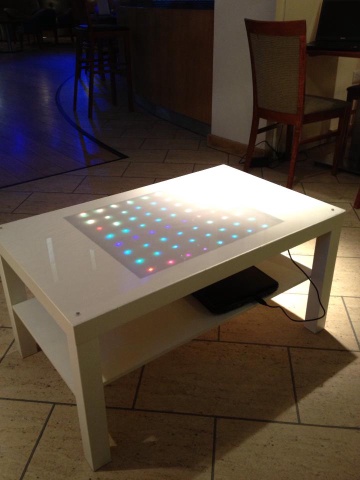
RGB Coffee Table.
Want to build an RGB LED coffee table? Here’s how you do it for £75! {% youtube 0ZUA9rlcdKs %}
{% row %} {% span 4 pull-right %} {% well %} {% capture sidebar %}
Shopping list.
- 1 x Ikea Table : £20.
- 64 x RGB LED : £7
- 1 x rainduino : £16.
- 1 x Acrylic sheet : £14
- 1 x Frosting spray : £4
- 1 x 3mm Hardboard : £5
Store Cupboard Stuff.
- 4 x colours of single core wire.
- 4 x self tapping screws
- 4 x washer
- Heat-shrink
Tools
- Solder.
- Solder Iron.
- Craft Knife.
- Ruler.
- Drill.
- 5mm drill bit. {% endcapture %} {{ sidebar | markdownify }} {% endwell %} {% endspan %}
The table is based around Ikea’s Lack coffee table, which is both super cheap and has some interesting properties. Firstly it is 19" wide, if you not sure why that is important you need to go see the LackRack! The other feature which makes it the perfect choice for hack is it’s interesting construction; the Lack is made from hardboard and cardboard so cutting it is easy.
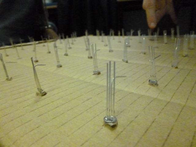
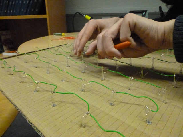
Step 1: LED jig.
You will need a platform to support your LEDs, mark out a 8 x 8 grid on a sheet of 3mm hard board*, drill 5mm hole on each point and place one LED in each hole making sure each LED has the same orientation.
{% row %} {% span 6 %}
{% endspan %} {% span 6 %}
{% endspan %} {% endrow %}
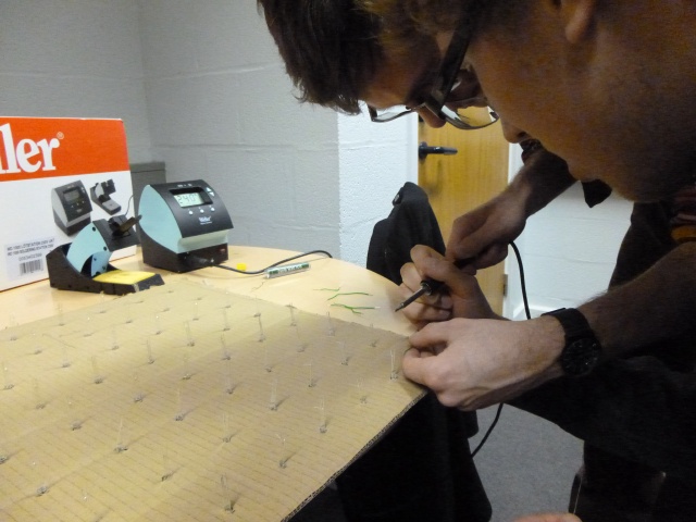
Step 2 : Solder the Array.
The array is wired up in a common anode matrix. This is the single most boring part of the construction; there are 64 x 4 joints to solder and heat shrink**.
{% row %} {% span 6 %}
{% endspan %} {% span 6 %}
{% endspan %} {% endrow %}
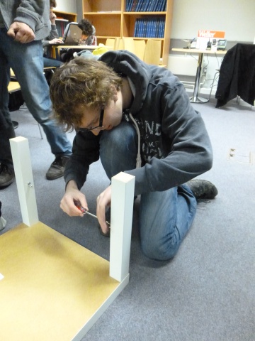
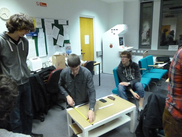
Step 3 : Prepare the Table.
The Lack table we used is cheap for a reason… it’s made from Cardboard! Mark up a square on your table big enough to hold your panel and use your craft-knife/Stanley to cut out the panel. Try and be neat about this, however if it’s not perfect don’t worry as it will be covered by the frosted acrylic later. Once you have removed the square you will find some corrugate cardboard inside the table remove this to make a cavity. You may also wish to make a hole hidden away for a USB cable to come out of.
Step 4 : Prepare the acrylic.
First Time to prepare the table top. First you will want to frost the acrylic on the back side by painting it with the frosting spray***. Before continuing make sure the back is fully dry. Next you will want to drill a hole 5 cm from each of the corners of the acrylic, you will use these to affix the acrylic to the table.
Step 5 : Finishing up.
Right time to put this all together. Drop your array into the table and screw on the top, use self tapping screws, however we found we did need a pilot hole.
Step 6: The Software.
The table really isn’t much good without a way to power it and provide pretty patterns, so we introduced Pixel Controller running on a computer. Pixel controller is a great real time matrix controller that can create some very beautiful patterns.
The Rainbowduino must be flashed with firmware in order to communicate with the Pixel Controller software, and that is available from a Google Code Rep and there is a full manual to walk you through setting it up, if you read German that is. For those that don’t the English Rainbowduino manual seems to be missing. However once you’ve flashed the firmware onto the ‘duino, the config file for Pixel Controller needs to editted to direct it to the correct COM port and then selecting the defaults as you choose.
Improvements
No project is really finished. We believe we could easily fit a second panel into the this table (or more if we doubled the pixel density). The rainbowduino supports this kind of multiplexing the only issue would be costs and time! *We used cardboard, which was what we had to hand, however the LEDs became loose during construction. ** We didn’t heat-shrink the joints as we didn’t have any at hand, however if we were to redo this project we would as it makes the joints much stronger and less likely to short. ***Again we cheated here and used a sheet of tracing paper. It does the job.
{% endrow %}